
Synopsys Cloud
Cloud native EDA tools & pre-optimized hardware platforms
Request a Free Trial →


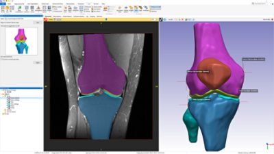
Improve confidence in clinical decision-making and pre-surgical planning. Simpleware ScanIP Medical is the ideal choice in a clinical setting, with FDA 510(k) market clearance and CE marking for medical use.
Learn More
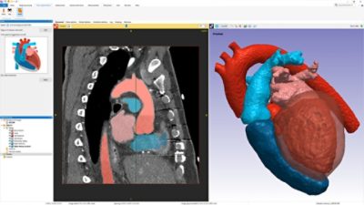
Reconstruct and analyze anatomical image data for biomedical research. Create high-quality models to study biomechanics applications, physiological flow simulations, and device design research.
Learn More
Visualize and explore 3D data for non-destructive testing and inspection of industrial parts. Understand and study materials structures for many types of metals, alloys, ceramics, composites and digital rock physics.
Learn MoreSignificantly reduce 3D image processing time with Simpleware automated AI/ML solutions. Discover our collection of anatomy-specific Auto Segmenter modules, as well as fully customizable options for different workflows or anatomies. Learn more.

Learn about the options available for generating high-quality models from 3D imaging data, including AI-powered segmentation. All licenses come with full support by our experienced Application Engineers.
SIGN UP FOR A FULLY SUPPORTED FREE TRIAL
SEE UPCOMING EVENTS AND SIMPLEWARE WEBINARS
READ CASE STUDIES, WATCH PRODUCT VIDEOS, DOWNLOAD DATASHEETS


Learn More


